CALCULATING "CHARGED" PIPES TO RAINWATER TANKS
This charged pipe calculator requires activation
To activate the full version you have two options:-
Purchase activation for all the extra features on this site Activate now
or if you have never purchased any of these programs before, you may activate a 2 day free trial of all the extra features on this site. Activate free trial
However, if you believe that you are registered but are using a different computer, or have lost the registration cookies, you can try re logging in here with youor original details. Login
Legend
Some text in red Italic, means click for further info.
Indicates a calculated field. User cannot change.
Indicates the Final Outlet.
Indicates a downpipe click for info
Indicates extra 'given' data inserted by the program. click for info
Indicates for information only
Indicates a calculated field. User cannot change.
Indicates the Final Outlet.
Indicates a downpipe click for info
Indicates extra 'given' data inserted by the program. click for info
Indicates for information only
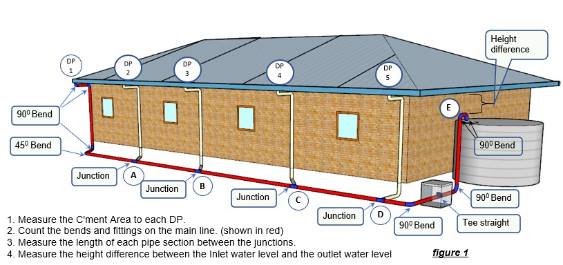
To Calculate: Press the 'Calculate Pipe Size' button. This can be done on any amount of input data.
Important Naming Conventions Example.
1. All catchments to be given only numbers. eg 1,2,3,4,...etc. DP's to have the corresponding number
2. All junctions, to be given only letters. eg A, B, .... etc
2. All junctions, to be given only letters. eg A, B, .... etc

Notes on "Charged Systems"
Most urban tanks should not be used for Potable water use.
Some Authorities make tanks mandatory, but stipulate that they can only be used for things like landscape, Toilets, sometimes laundry etc. Serious backflow devices must be used, and all outlets labled "Non Potable". Charged systems in particular should not be used for potable water use.
Notes on using the program
Clicking on any input cell may erase all answers associated with that cell.
This is done to hopefully prevent users from unknowingly accepting a previous answer, and to encourage a recalculation.
However nothing is committed to memory until a submit button is pressed.
So all erased data can be recovered by refreshing the page.
It doesn't act like a spreadsheet, pressing the enter key does not do anything.
Catch 22
This is the typical catch 22 problem, or as they say in excel a circular reference.
We have to find the pipe sizes that will drain to the tank.
To do this we have to find the friction loss. We then have to make sure it is less than the height difference from the obvert of the outlet to the underside of the eaves gutter.
But to find the friction loss we have to know the pipe size.
Which is what we are trying to find out!!.
Any suggestions?
We have to do it by trial and error.
If we have only one downpipe its easy, as there are only 3 or four sizes to choose from.
90, 100, 150, and if you are really desperate 225 mm dia.
What if there is more than one DP?
 The program allows for any number of DP's.
Step one is to analyze the head loss through the minimum pipe size of all sections. The minimum pipe size is taken from the DP size at each junction.
There must be no pipe down stream smaller than the largest downpipe entering upstream.
The flow in each section is not considered at this stage.
If the head loss is too great, the whole thing starts to get interesting.
We have to find a way of increasing some or all of the pipe sizes.
We could randomly pick a pipe section here and there and increase that; but this requires user input. Users doing random changes can lead to stuff ups, I'd rather have the program do it.
Not necessarily the stuff up part.
So the program decreases the hydraulic grade ie makes the grade flatter.
A flatter grade needs a larger pipe to carry the same flow. This means less velocity, which means less friction, which means less head loss.
We keep decreasing the grade until we can reduce the head loss to less than the height difference between the bottom of the eaves gutter, and the obvert level of the outlet into the tank. Or the top water level in the tank if the pipe enters in the side of the tank.
What if we want to drain both sides of the roof into the tank?
The best way to do this is to drain both sides separately to the tank, with two separate calculations. As in Fig1.
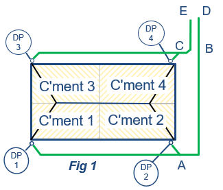
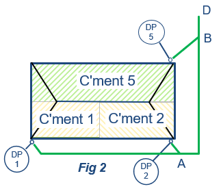
However if for some inexplicable reason you want to join both sides together somewhere, and take only one line from the junction to the tank, as in fig2, then calculate each side separately as above, to get all pipe sizes.
Pick which side is the worst case, (ie the longest length or lowest upstream gutter).
Join all these pipes together in the pipeline table.
However when you get to the spot where the other side joins the main pipe, as in point B in fig2, assume all catchments on this other side, drain to one fictitious DP. as in DP5 in fig2
Enter this DP, and its total catchment area, into the catchment table, and join it to this junction (B) in the pipeline table.
This will have the effect of entering all the flow from the other side into this point.
However, for large projects, joining pipes like this is not recommended as it creates problems with clean-outs and maintenance.
It may be time to consider an underground tank, and drain all pipes to it by gravity in the normal manner.
What is the best solution for large jobs?
Usually in large industrial, commercial, or multi unit jobs it is best to install an underground tank. Such a tank can usually be placed under a road, or other public area.
What if this gives us ridiculously large pipes?
The answer is to lower the top of the tank. or lower the pipe entering the tank by bringing it into the side of the tank at the top. In this case the exit water level for the height difference calculation will be the top water level in the tank.
Or just give up and put the tank underground.
What if the first downpipe size has been increased?
Is the pipe siphonic?
In technical terms it is called an inverted siphon. And yes it can be designed as a siphon.
However doing this can result in the inground pipes being much smaller than the DP's.
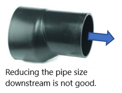 This is not good, and is a blockage waiting to happen.
We could make the DP's siphonic, but this requires special fittings, and the whole thing can get out of hand trying to fit those fittings into an eaves gutter.
Also the powers that be will certainly raise a few eyebrows.
However for very large roofs and wide gutters it may be worthwhile talking to the siphonic people.
They have done tests on all their stuff and can produce a performance solution.
Plumbing Codes
To try and make it easy for the certifiers, the program takes all calculations from various Plumbing codes.
AS/NZS 3500.3 The storm water Code, for DP sizing.
AS/ZS 3500.1 The water supply Code, for pipes flowing full.
AS 2200 - Design charts for water Supply and Sewerage, for calculating the head loss through bends and fittings.
So all calculations are deemed to satisfy the relevant sections of these codes, and can be easily checked.
What is a Charged pipe?
A "Charged" pipe is a pipe that drains a roof to a tank, but takes a dip underground first, before rising to the top of the tank.
When the rain stops, this pipe will retain water in the dip section. This is called being "charged".
When the pipe is flowing full it is under a little bit of pressure.
A pressure pipe does not have a grade like a storm water pipe. It acts more like a water pipe.
However all pipe sizing formulas require a grade. This grade is called the hydraulic grade. And is the head (height) difference between the water level at the inlet and outlet, divided by the length of pipe between.
Some other requirements.
Because a charged pipe remains full of water, there should be some way of cleaning it out if it all goes horribly wrong. It is best to put an inspection opening in a pit at a low point somewhere, and grade all pipelines at the minimum required grade to this point.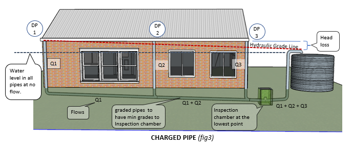
The program gives the approximate total volume of water left in the charged pipes.
A certain percentage of this water will come out of the inspection opening when it is opened.
This water will be mainly in the vertical sections. The program gives an approximation of this volume.
However it is advisable to check this volume manually if this volume is critical to your design.
Cleanouts and inspection openings It is useful to contemplate where this water (and possibly rubbish) will go when you open the inspection opening.
It could be advantageous to make the Inspection Chamber big enough to store most of it. Then bucket, or pump it out, or let it soak in, and remove any rubbish later.
You may wish to place the cleanout tee on its side, reduce the pipe to say 50mm, and put a ball valve (swimming pool valve) on it, and pipe the flow to a suitable point.
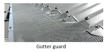
If there is a likelihood of rubbish collecting in the charged pipe, it is advisable to install gutter guards on all gutters draining to the tank.
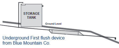
You may wish to investigate installing a first flush device.
Here is a device from Blue Mountain Co that has been designed for this purpose.
In line filters are also available. If you use these, you will need to obtain a "k" value for this from the Manufacturer. Or if the Manufacturer can only give you a head loss, you can calculate the "k" value from the formula k = (HL*2g) / V^2
Add this "k" value to the column "Other k value" in the above table.
Playing around.
Sometimes it may seem unusual that the head loss in the charged system is a lot less than is available. Meaning that the program should be able to use smaller pipes, to increase the head loss to something closer to the available head loss.
So have a play around with the height difference, and see the changes that it makes to the pipe size, and the corresponding head loss.
The difference is caused by the program having to go to a larger pipe.
For instance if the program calculates that a 110 pipe is required, it must use to the next available pipe which is 150 dia, which has a substantially lower head loss.
Just so it is not completely ridiculous, the program only rounds up if the calculated size is greater than 2% of the available diameter.
Most urban tanks should not be used for Potable water use.
Some Authorities make tanks mandatory, but stipulate that they can only be used for things like landscape, Toilets, sometimes laundry etc. Serious backflow devices must be used, and all outlets labled "Non Potable". Charged systems in particular should not be used for potable water use.
Notes on using the program
Clicking on any input cell may erase all answers associated with that cell.
This is done to hopefully prevent users from unknowingly accepting a previous answer, and to encourage a recalculation.
However nothing is committed to memory until a submit button is pressed.
So all erased data can be recovered by refreshing the page.
It doesn't act like a spreadsheet, pressing the enter key does not do anything.
Catch 22
This is the typical catch 22 problem, or as they say in excel a circular reference.
We have to find the pipe sizes that will drain to the tank.
To do this we have to find the friction loss. We then have to make sure it is less than the height difference from the obvert of the outlet to the underside of the eaves gutter.
But to find the friction loss we have to know the pipe size.
Which is what we are trying to find out!!.
Any suggestions?
We have to do it by trial and error.
If we have only one downpipe its easy, as there are only 3 or four sizes to choose from.
90, 100, 150, and if you are really desperate 225 mm dia.
What if there is more than one DP?
The program allows for any number of DP's.Step one is to analyze the head loss through the minimum pipe size of all sections. The minimum pipe size is taken from the DP size at each junction.
There must be no pipe down stream smaller than the largest downpipe entering upstream.
The flow in each section is not considered at this stage.
If the head loss is too great, the whole thing starts to get interesting.
We have to find a way of increasing some or all of the pipe sizes.
We could randomly pick a pipe section here and there and increase that; but this requires user input. Users doing random changes can lead to stuff ups, I'd rather have the program do it.
Not necessarily the stuff up part.
So the program decreases the hydraulic grade ie makes the grade flatter.
A flatter grade needs a larger pipe to carry the same flow. This means less velocity, which means less friction, which means less head loss.
We keep decreasing the grade until we can reduce the head loss to less than the height difference between the bottom of the eaves gutter, and the obvert level of the outlet into the tank. Or the top water level in the tank if the pipe enters in the side of the tank.
What if we want to drain both sides of the roof into the tank?
The best way to do this is to drain both sides separately to the tank, with two separate calculations. As in Fig1.
However if for some inexplicable reason you want to join both sides together somewhere, and take only one line from the junction to the tank, as in fig2, then calculate each side separately as above, to get all pipe sizes.
Pick which side is the worst case, (ie the longest length or lowest upstream gutter).
Join all these pipes together in the pipeline table.
However when you get to the spot where the other side joins the main pipe, as in point B in fig2, assume all catchments on this other side, drain to one fictitious DP. as in DP5 in fig2
Enter this DP, and its total catchment area, into the catchment table, and join it to this junction (B) in the pipeline table.
This will have the effect of entering all the flow from the other side into this point.
However, for large projects, joining pipes like this is not recommended as it creates problems with clean-outs and maintenance.
It may be time to consider an underground tank, and drain all pipes to it by gravity in the normal manner.
What is the best solution for large jobs?
Usually in large industrial, commercial, or multi unit jobs it is best to install an underground tank. Such a tank can usually be placed under a road, or other public area.
What if this gives us ridiculously large pipes?
The answer is to lower the top of the tank. or lower the pipe entering the tank by bringing it into the side of the tank at the top. In this case the exit water level for the height difference calculation will be the top water level in the tank.
Or just give up and put the tank underground.
What if the first downpipe size has been increased?
- If it will still fit in the gutter, you may choose to accept it.
- You can put a rainwater head (or sump) of the required depth in the eaves gutter to fit the DP.
- You could lower the outlet top water level, as suggested above.
- You could try putting a node at the base of the DP, thereby creating another pipe section. This may be sufficient to leave the DP unchanged, especially if there is only one down pipe.
Is the pipe siphonic?
In technical terms it is called an inverted siphon. And yes it can be designed as a siphon.
However doing this can result in the inground pipes being much smaller than the DP's.
This is not good, and is a blockage waiting to happen.We could make the DP's siphonic, but this requires special fittings, and the whole thing can get out of hand trying to fit those fittings into an eaves gutter.
Also the powers that be will certainly raise a few eyebrows.
However for very large roofs and wide gutters it may be worthwhile talking to the siphonic people.
They have done tests on all their stuff and can produce a performance solution.
Plumbing Codes
To try and make it easy for the certifiers, the program takes all calculations from various Plumbing codes.
AS/NZS 3500.3 The storm water Code, for DP sizing.
AS/ZS 3500.1 The water supply Code, for pipes flowing full.
AS 2200 - Design charts for water Supply and Sewerage, for calculating the head loss through bends and fittings.
So all calculations are deemed to satisfy the relevant sections of these codes, and can be easily checked.
What is a Charged pipe?
A "Charged" pipe is a pipe that drains a roof to a tank, but takes a dip underground first, before rising to the top of the tank.
When the rain stops, this pipe will retain water in the dip section. This is called being "charged".
When the pipe is flowing full it is under a little bit of pressure.
A pressure pipe does not have a grade like a storm water pipe. It acts more like a water pipe.
However all pipe sizing formulas require a grade. This grade is called the hydraulic grade. And is the head (height) difference between the water level at the inlet and outlet, divided by the length of pipe between.
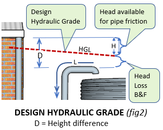
As can be seen in figure 2, the total height difference (D) is the distance between the underside of the eaves gutter,
and the obvert of the outlet pipe.
This is the total amount of head loss that is allowed for friction in the pipe and fittings.
There are two separate calculations, one for the pipe friction loss, and another for the friction loss due to the bends and fittings.
Subtracting the head loss due to the bends and fittings from the total available (D), gives the head loss (H) available for pipe friction.
Dividing this figure by the pipe length (L) gives the hydraulic grade.
This is the grade used in all the pipe design formulas.
Some other requirements.
Because a charged pipe remains full of water, there should be some way of cleaning it out if it all goes horribly wrong. It is best to put an inspection opening in a pit at a low point somewhere, and grade all pipelines at the minimum required grade to this point.
The program gives the approximate total volume of water left in the charged pipes.
A certain percentage of this water will come out of the inspection opening when it is opened.
This water will be mainly in the vertical sections. The program gives an approximation of this volume.
However it is advisable to check this volume manually if this volume is critical to your design.
Cleanouts and inspection openings It is useful to contemplate where this water (and possibly rubbish) will go when you open the inspection opening.
It could be advantageous to make the Inspection Chamber big enough to store most of it. Then bucket, or pump it out, or let it soak in, and remove any rubbish later.
You may wish to place the cleanout tee on its side, reduce the pipe to say 50mm, and put a ball valve (swimming pool valve) on it, and pipe the flow to a suitable point.
If there is a likelihood of rubbish collecting in the charged pipe, it is advisable to install gutter guards on all gutters draining to the tank.
You may wish to investigate installing a first flush device.
Here is a device from Blue Mountain Co that has been designed for this purpose.
In line filters are also available. If you use these, you will need to obtain a "k" value for this from the Manufacturer. Or if the Manufacturer can only give you a head loss, you can calculate the "k" value from the formula k = (HL*2g) / V^2
Add this "k" value to the column "Other k value" in the above table.
Playing around.
Sometimes it may seem unusual that the head loss in the charged system is a lot less than is available. Meaning that the program should be able to use smaller pipes, to increase the head loss to something closer to the available head loss.
So have a play around with the height difference, and see the changes that it makes to the pipe size, and the corresponding head loss.
The difference is caused by the program having to go to a larger pipe.
For instance if the program calculates that a 110 pipe is required, it must use to the next available pipe which is 150 dia, which has a substantially lower head loss.
Just so it is not completely ridiculous, the program only rounds up if the calculated size is greater than 2% of the available diameter.
Contact
If you find that the programs save you heaps of agro, please feel free to buy me a few beers.